DETR : End-to-End Object Detection with Transformers
Highlights
- DEtection TRansformer (DETR) is a new transformer-based model to perform object detection in an end-to-end fashion.
- The main idea of the paper is to force unique predictions via bipartite matching that finds the optimal assignment between the predicted bounding boxes and the ground truth, avoiding the use of surrogate components or post-processing like non-maximum suppression or anchors.
- It combines a CNN-based feature extraction with a transformer encoder-decoder architecture1.
- Code is available on this GitHub repo.
Introduction
The goal of object detection is to predict a set of bounding boxes and category labels for each object of interest. Modern detectors address this set prediction task in an indirect way, by defining surrogate regression and classification problems on a large set of proposals, anchors, or window centers. Their performances are significantly influenced by postprocessing steps to collapse near-duplicate predictions, by the design of the anchor sets and by the heuristics that assign target boxes to anchors.
The authors propose to simplify this pipeline and avoid surrogate tasks by a direct set prediction approach.
Model architecture
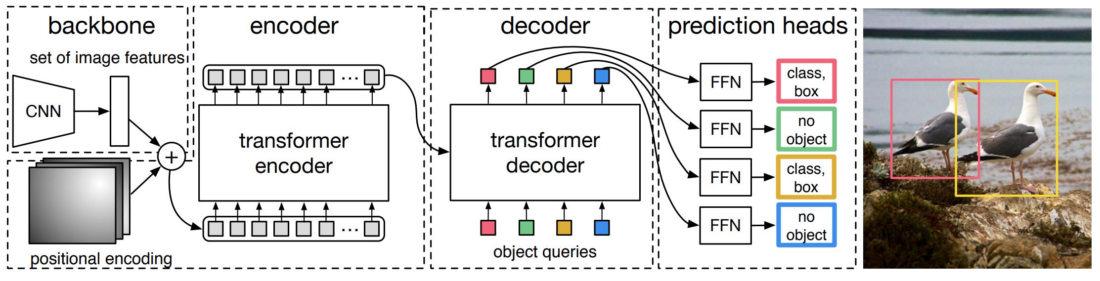
Figure 1. High-level overview of DETR architecture.
DETR model is composed of 4 main parts :
- a CNN backbone feature extractor
- a transformer encoder that acts on the features extracted by the backbone CNN
- a transformer decoder that performs cross-attention between object queries and visual features output by the image encoder
- a prediction head that converts the outputs of the decoder to position and class bouding boxes predictions
Figure 1 gives a high-level overview of the architecture of DETR and figure 2 illustrates it more precisely. The details of DETR’s architecture are discussed in the following subsections.
Feature extractor
Given an input image \(x \in \mathbb{R}^{3 \times H_0 \times W_0}\), an ImageNet-pretrained ResNet-50 or 101 is used to extract visual features \(f \in \mathbb{R}^{2048 \times \frac{H_0}{32} \times \frac{W_0}{32}}\). Note that this module could be replaced by a classical patch extractor (usually parametrized by a unique strided convolution) but extracting features from a model pretrained on natural images yields better results.
Transformer Encoder
The image encoder is a stack of transformer encoder blocks, where multi-head self-attention is performed between image tokens. It has a slight modification from the original architecture as a fixed sinusoidal positional encoding is added at each block. A 1x1 convolution precedes the encoder to reduce the input feature size from \(C\) to \(d\).
Transformer Decoder
The inputs of the decoder are \(N\) embeddings of size \(d\). \(N\) represents the maximum number of possible object predicted in an image, and each embdding represents a future bounding box predicted by the network (after the decoder and the feed-forward prediction head).
To be more precise, the input embedding are learnt positional encodings, in this context also called object queries.
Contrary to the original architecture, there is no masking in the decoder, i.e. the model is not auto-regressive.
Prediction feed-forward networks
The final prediction is computed by a 3-layer perceptron with ReLU activation function and hidden dimension d. A first linear layer outputs 4 scalars to represent the normalized center coordinated, height and width of the box, and a second linear layer predicts the class label associated with the box using a softmax function.
It is important to note that each embedding output by the decoder is decoded independently from the others.
Since there are generally less than \(N\) objects present in the image, an additional class \(\emptyset\) (“no object”) is added.
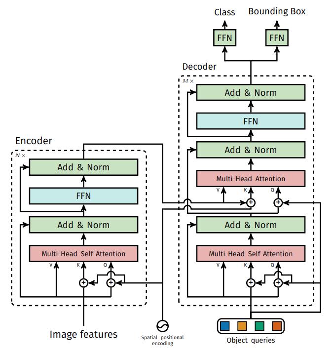
Figure 2. Details of the encoder-decoder architecture of DETR.
Object detection set prediction loss
Since the model aims to get rid of the anchors box and non maximum suppression mechanism, it has to find a clever way to predict all the object in a single forward pass.
Let’s denote \(y=\{ y_i\}\) the ground truth set of objects of an image and \(\hat{y} = \{ \hat{y}_i \}_{i=1}^N\) the set of N predictions. As \(N\) is generally larger than the number of objects in the image, \(y\) is padded to a set of size \(N\) with the labels \(\emptyset\).
The loss procedure first looks for an optimal bipartite matching between the ground truth and the prediction sets, i.e. the goal is to find a permutation \(\\sigma \in \mathcal{S}_N\) with the lowest cost :
\[\hat{\sigma} = \underset{\sigma \in \mathcal{S}_N}{\arg \min} \sum_{i}^{N} \mathcal{L}_{match}(y_i, \hat{y}_{\sigma(i)})\]where \(\mathcal{L}_{match}(y_i, y_{\sigma_i})\) is a pairwise cost between between a ground truth bounding box \(y_i\) and a predicted bounding box \(y_{\sigma(i)}\). This optimal permutation can be computed efficiently with the Hungarian algorithm.
In the case of object detection, the matching cost must take into account both the coordinates/height/width and the class of the bounding boxes. It is defined as follows :
\[\mathcal{L}_{match} (y_i, \hat{y}_{\sigma (i)}) = \unicode{x1D7D9}_{ \{ c_i \notin \emptyset \} } \hat{p}_{\sigma (i)} (c_i) + \unicode{x1D7D9}_{ \{ c_i \notin \emptyset \} } \mathcal{L}_{box} (b_i, \hat{b}_{\sigma (i)})\]with \(c_i\) the class of the ground truth bounding box \(b_i \in [ 0, 1] ^{4}\) and \(\hat{p}_{\sigma (i)} (c_i)\) the probability of the for bounding box \(\hat{b}_{\sigma (i)}\) for the class \(c_i\).
\(\mathcal{L}_{box}(\cdot, \cdot)\) is a loss to compare vectors of \(\mathcal{R}^4\) that represent the normalized center coordinates, width and height of a bounding box. It is defined as follows :
\[\mathcal{L}_{box} (b_i, \hat{b}_{\sigma (i)}) = \lambda_{iou} \mathcal{L}_{iou} (b_i, \hat{b}_{\sigma (i)}) + \lambda_{L1} \lVert b_i - \hat{b}_{\sigma (i)} \rVert _1\]with \(\lambda_{iou}\) and \(\lambda_{L1}\) two hyperparameters set respectively to 2 and 5 in the experiments presented later.
Note that this whole process is detached from the computational graph that will be used for backpropagation.
Once the best permutation \(\hat{\sigma}_i\) is found, the Hungarian loss is computed for all pairs matched in the previous steps and is then used to compute the gradients in the network. The loss is a combination of negative log-likelihood for class prediction and the box loss defined earlier, only for the predicted bounding boxes that have been assigned to real non-empty bounding boxes in the ground truth. More precisely, it is computed as follows:
\[\mathcal{L}_{Hungarian}(y, \hat{y}) = \sum_{i=1}^{N} [ - \log \hat{p}_{\hat{\sigma} (i)} (c_i) + \unicode{x1D7D9}_{ \{ c_i \notin \emptyset \} } \mathcal{L}_{box} (b_i, \hat{b}_{\hat{\sigma} (i)}) ]\]The authors found helpful to use additional losses inside the decoder during training. They added prediction FFNs (N.B: all the FFNs share the same parameters) and Hungarian loss after each decoder layer.
Results
- Qualitative and quantitative evaluation on COCO 2017 dataset. 118K training images and 5K validation images.
- They are 7 instances per image on average and up to 63 instances in a single image of the training set.
- The maximum number of predictions, \(N\), is consequently set to 100.
- Results are compared to Faster R-CNN, the strongest baseline for real-time object detection on natural images
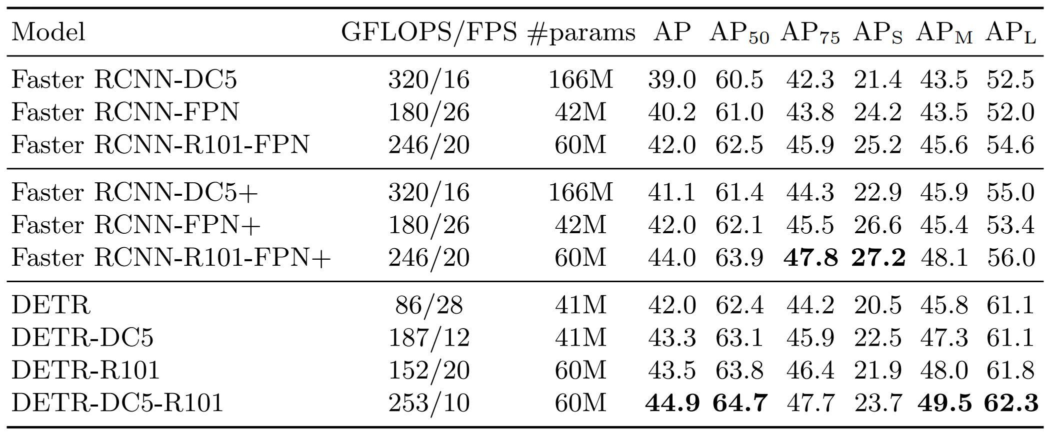
Table 1. Performances comparison with Faster R-CNN on COCO 2017 dataset.
Recall that FFNs prediction heads and Hungarian loss were used at each decoder stage during training. The authors computed the performances at each decoder layer, showing that the performances of the deepest layers are not improved by bounding boxes post-proccessing techniques such as Non-Maximum Suppression.
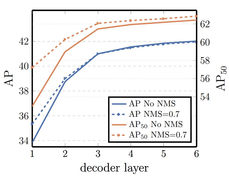
Figure 3. Performances at each decoder stage.
The two figures below show the attention of the encoder and the decoder for a reference point or for the final predicted object.

Figure 4. Encoder self-attention for several reference points (in red).
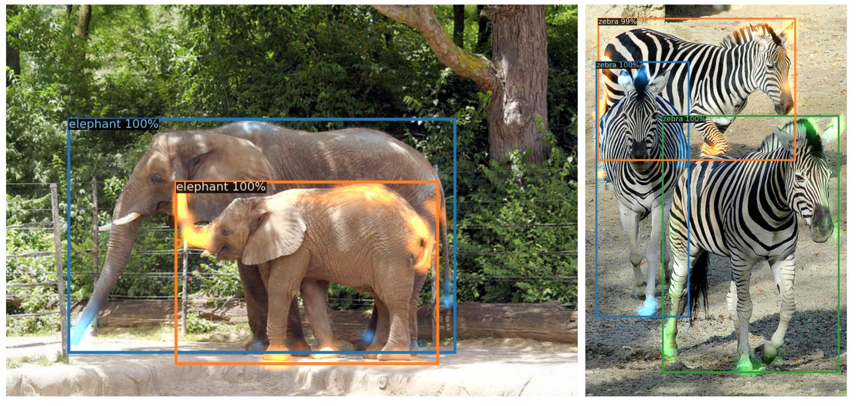
Figure 5. Decoder attention for every predicted object.
With small modifications that create a FPN-like network, DETR can also work for panoptic segmentation (details not explained here, we only provide an exemple of visual results below)

Figure 6: Qualitative results for panoptic segmentation generated by DETR-R101.
Conclusion
DEtection TRansformer (DETR) is a new transformer-based model to perform object detection in an end-to-end fashion. The main idea of the paper is to force unique predictions via bipartite matching that finds the optimal assignment between the predicted bounding boxes and the ground truth, avoiding the use of surrogate components or post-processing like non-maximum suppression or anchors.
References
-
A. Vaswani, N. Shazeer, N.. Parmar, J. Uszkoreit, L. Jones, A. N. Gomez, L. Kaiser, I. Polosukhin, Attention Is All You Need, NeurIPS 2017, link to paper ↩